Manufacturing Sub-Team Exercises and Resources
Overview
The Manufacturing Sub-Team is responsible for making the custom parts that are needed for the robot using the various tools available in the RAHS Shop.
Drill Press
Manual Lathe
Manual Mill
3D Printer
The Makerbot Method printers can now use the Ultimaker Cura software starting with version 5.7 (Download Here). This is significantly better way to slice models for printing on the Method and Method X printers. It is also possible to integrate the launching of Cura from within Fusion 360 when you want to 3D print a model.
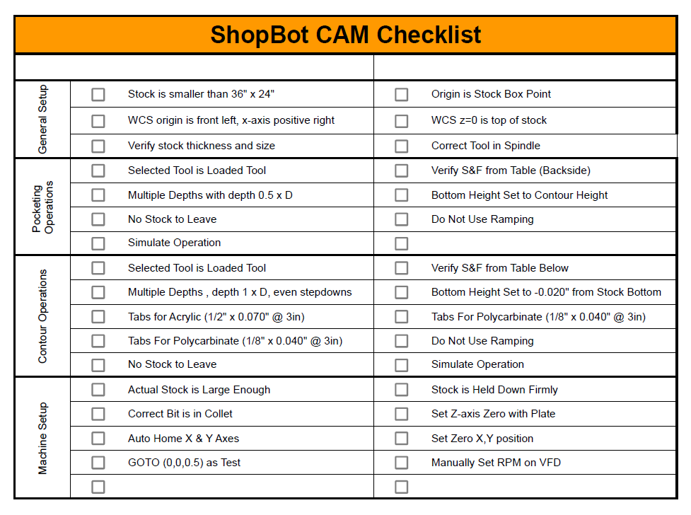
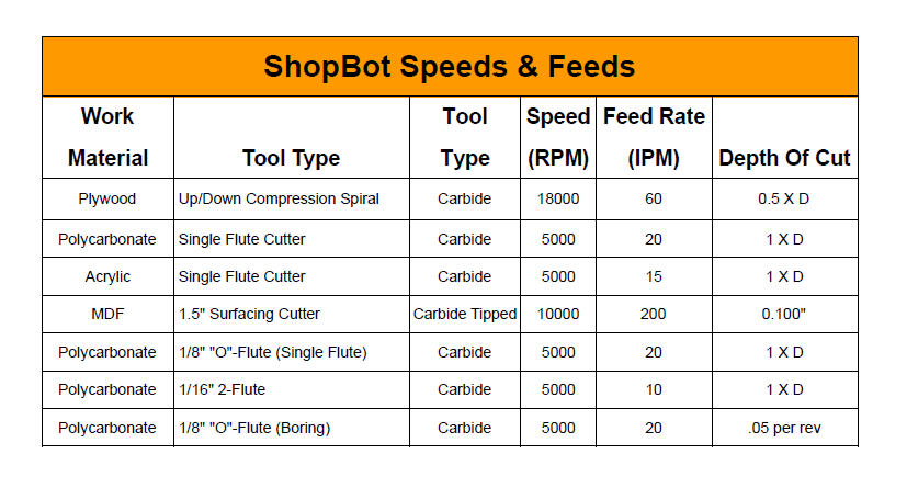
ShopBot


HAAS Mill
G-Code
G-Code is the computer numerical control (CNC) programming language used to control the Haas Mill. The G-Code program tells the machine where to move, how fast to move, how fast to spin the spindle, when to do tool changes etc. G-Code is usually generated automatically using a post-processer from the CAM software used to design a part. It is however possible to write simple G-Code programs by hand.
CNC Coordinate Systems
G-code programs always use a coordinate system that is relative to some feature on the part being machined or to an edge of the raw stock used. The CNC machine doesn’t know where the part is located in the machine without being told.
The Work Coordinate Systems (WCS) are used to tell the Haas where the part is in the machine. There are several WCSs available for the G-code program to use but the first one (G54) is the most commonly used. There are also G55-G59 and some others. The WCS has X, Y, & Z Offsets that correspond to the location of the part origin point in the Machine Coordinate System (MCS). When a WCS is selected (using G54 or G55 etc) the Haas adds the WCS offsets to all the coordinates (X,Y,Z) to determine the machine coordinates.

Tool Offsets
The X and Y axes are straight forward, however the Z-axis has the added complication that the CNC machine uses different tools and each tool is a different length. Each tool used in a G-Code program must have a the correct tool offset associated with it. When a tool offset is enabled (G43 H01 for example) the tool offset value (H value) is added to the Z-coordinate in addition to the WCS Z value.
Tool offsets can be set up using either the top of the part as the datum or a Z-axis setter as the datum. There are many advantages to using a Z-axis setter and that method should be used. When a datum other than the part is used to determine the tool offsets, they only need to be determined once. They would only need to be changed when the tool breaks or it is removed from the machine and the H-value is not remembered.

When the Z-axis setter method is used the distance from the top of the Z-Setter to the Part Z-origin needs to be determined for each new part that is machined (WCS Z). However, the tool offsets do not need to be redone. A dial indicator or the Haimer may be used to measure the WCS Z value.
Feeds and Speeds

Resources
-
Drill/Tap/Clearance Hole Chart (Metric in the Printable Version)